About this deal
Then I saw level shifter like a TXB0104 - would that be something where I could simply connect RX/TX/VCC/GND on both sides and turn my brain off? In the IDE, go to File/Examples/Basics/Blink and load the sketch. If you have performed the previous steps correctly, the IDE should be able to communicate with the Arduino and upload the sketch. Eventually you will see LED 13 (on the board, blue) flashing once per second. Blue LED on board flashes once per second (with “blink” sketch) WARNING: by installing a new version of the Arduino IDE you risk overwriting the CH340G drivers. For this reason we suggest you not to install the IDE using the executable (.exe) but to use a “portable” version. If you accidentally overwrite the CH340G drivers, uninstall the IDE with the drivers and reinstall everything from scratch. So my first idea was to buy a (maybe isolated) USB adapter and putting it in a heavy enclosure with a selection switch that makes it very obvious the voltage was.
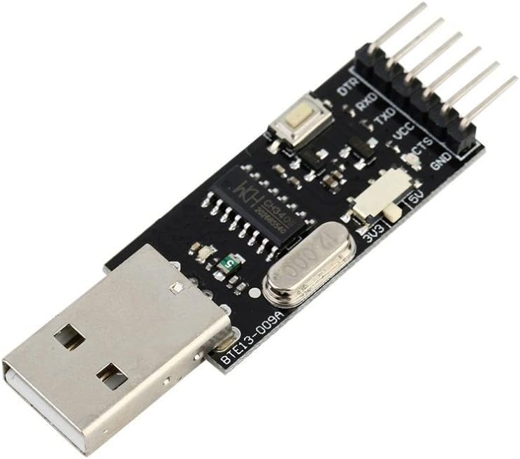
We specify that this procedure works with devices that already have a bootloader installed inside them. We have never loaded a bootloader but on the Internet there are many tutorials on the subject, such as: This instructable is a combination of all options in one box and its built from over 90% recycled parts so its Eco friendly, hence the name. I recently posted an instructable for an FLDigi compatible interface. It was largely based on a Hamcomm interface I designed as a hand out for a Ham / PC Usergroup talk I gave in 2005. However, if you look at the CH340 datasheet, the same board can be modified to change both the Vcc and the data pins voltage from the same switch, but you'll have to cut a few traces and rewire. I modified mine, but can not find the schematic with the changes right now. It was only a few traces to rewire as seen in the pics, and now it switches both the power and the data levels. In the attached CH341SER_LINUX.ZIP file, there is a file called readme.txt which contains the detail of all the steps to follow. Note that these drivers support a kernel version from 2.6.65 to 3.13.x.
4 Comments
As said you can try rebooting your computer and see if that helps…I never had to myself for my diode laser but…I have had to for other driver installs so…can’t hurt. Computers are funny things. You want to use unidirectional voltage level translators or isolators for UART and SPI, and not bidirectional ones, as the latter tend to have glitches (in the low level signal part, when the direction sensing circuitry isn't sure of what is going on) in this kind of use that can cause transmission errors. So, I'd say forget TXB chips, and all bidirectional voltage level conversion chips. soldering material and equipment (in this regard you can watch our tutorial Yet another tutorial on how to solder) Turns out that the driver isn’t signed and in Yosemite, driver files must be signed to be used. There’s a command we can issue to bypass this. If you buy your own FTDI chip, go for something that has two serial ports, e.g. FTDI FT2232H, those are often used as JTAG interface with an additional serial port, too.
This procedure is valid for all Serial – USB converters based on the CH340G USB-to-Serial. Installing drivers for CH340G on Windows 7 The power_saving_init() should be the first thing to be called at setup(), it will initialize all your pins to LOW. power_saving_sleep() will put everything to sleep, and wake up every 8 seconds. With these two, with the regular board (no bootloader modifications, with the power regulator on, etc) when sleeping I was able to achieve 3.24mA of power consumption, which is already pretty good considering it was draining about 10.2mA when fully powered on in the first place. As said in the introduction, in this step we won’t explain how to solder because it would make the tutorial too long and, above all, because we already covered this topic in our first tutorial. So, take a look at it if you want to know more about soldering.
C media cmi8738 c3dx audio driver v2 75a for windows xp driver
While Arduino is placed on the breadboard, only solder the four vertex joints. Why only four vertex? Because breadboard is made of plastic and if you accidentally hit it with your iron solder tip you’ll damage it. Simply put…the computer is not even seeing anything plugged into the comm port. trying to do any more communication is pointlesss. Like not getting a dial tone on a phone…trying to continually dial out is an effort in futility. The first one I killed when I used a USB TTL adapter that I believe kept the TTL signal level at 5V even when selecting 3.3V. Arduino clones need specific drivers, different from the standard ones that come with the Arduino IDE
But it doesn’t end here! That’s were the Power Cutter comes in. Thanks to Talpa PCB retrace of the BTE13-010 I was able to elaborate an evil power saving plan: This is a simple guide that will teach you how to take the first steps with the BTE13-010 module, a cheap Arduino mini clone. We will go through the 4 basic steps necessary to get it working immediately and without problems: I now use TI TXU0202 in VSSOP-8 for this. Before, I used to use TI SN74LVC1T45's in SOT23-6, which can be easier to work with, as VSSOP-8 has 0.5mm pitch, whereas SOT23-6 has almost 1mm pitch, and can even be dead-bugged (soldered directly to thin wires in air). TXU0202 can handle either side with logic levels between 1.1V and 5.5V, which means it's pretty darn good for this. I also use the related TXU0304 in TSSOP-14 for SPI.http://kiguino.moos.io/2014/12/31/how-to-use-arduino-nano-mini-pro-with-CH340G-on-mac-osx-yosemite.html Often the FTDI based ones are preferred. The FTDI chip is very expensive in comparison with other USB to TTL bridges, but they are often preferred. So look for FTDI when searching USB to TTL. Often FTDI ones use fake clones instead of the genuine and expensive FTDI, so if it's too cheap then it's probably not genuine FTDI. I would stay with Laser GRBL open for testing until you can establish connections with it since to me it is easier to work in for diagnostics. Once LAser Grbl can comm with the laser and comp then you can swap over to LB.
Soldering headers can be pretty easy if you take advantage of a breadboard. Place them on it and then put Arduino over connectors. Global variables use 9 bytes (0%) of dynamic memory, leaving 1,015 bytes for local variables. Maximum is 1,024 bytes. Before uploading the sketch, set the correct Arduino model, its microcontroller and the used COM port. See the screenshots below to see where these settings are located.Bus 002 Device 002: ID 174c:55aa ASMedia Technology Inc. Name: ASM1051E SATA 6Gb/s bridge, ASM1053E SATA 6Gb/s bridge, ASM1153 SATA 3Gb/s bridge, ASM1153E SATA 6Gb/s bridge I have also found that these drivers work fine when connecting the LoLin NodeMCU V3 to my Windows 7 PC (I had to do nothing, since I had already loaded the drivers for my cheap Chinese Arduino Nano clones). I suspect the same will be true for the Amica v0.9 (yellow or blue PCB) NodeMCUs (both considered out-dated) and the DoIt/SmartArduino brand NodeMCU V2. Both of these boards also use a WCH CH340G USB-to-UART bridge chip.
 Great Deal